February 04, 2014 / by Robin Scheibler / 4 comments
Make a custom Pomodoro timer
I have recently been interested in the ATtiny85 microcontroller. Its minimalistic, yet powerful features make it a very attractive platform for simple hacks and gadgets. In addition, I had been interested in learning the technique of charlieplexing, i.e. controlling many LEDs with very few pins. The ATtiny85, with its 5 GPIO pins available by default (sacrificing ISP yields an extra pin, but I didn’t want to go down that road), seemed like the perfect candidate.
I decided to build a custom timer for the pomodoro technique. This is a technique to increase productivity by splitting time into slices of 25 minutes of work followed by a 5 minutes rest period. The technique proposes normally to use a tomato shaped kitchen timer to keep track of time, but I will be designing and building my own.
All the schematics, board files, and firmware are available in the project github repo. Feel free to reuse anything!
The design
We lay down here the basic design for our project. Our pomodoro timer will need the following components to be useful.
- Time keeper The primary feature necessary for a timer is something to keep track of time. To minimize part count and save some pins, we will not rely on an external crystal. Instead, we use the ATtiny85 TIMER1.
- User interface A user interface is needed in order to start and stop the timer. Our minimalistic interface will be a single tactile switch. Here, I also decided to avoid a main power switch. Instead, the AVR will go into deep sleep, which should be energy efficient enough for this project. To wake up from sleep, the tactile switch is connected to INT0
- Feedback A buzzer is need to give a discrete signal when the timer expires. The buzzer is driven by TIMER0 in PWM mode at 4 kHz, 50% duty cycle. I picked an SMD buzzer that does not have a built-in driver, so I needed to add a few components for this.
- Extra fun As many LEDs as possible to indicate the progress of the timer. By default, the ATtiny85 has 5 GPIO pins (we could add an extra one, but would lose ISP). We have thus 3 GPIO remaining. We assign all of them to LEDs and using charlieplexing, it is possible to drive 6 LEDs using only 3 pins. We choose 5 yellow, for every 5 minutes slice of the first timer, and a single red one, for the rest time of the second timer.
- Power The board is powered by a CR2032 lithium coin cell. These have plenty of juice and a sleek low profile.
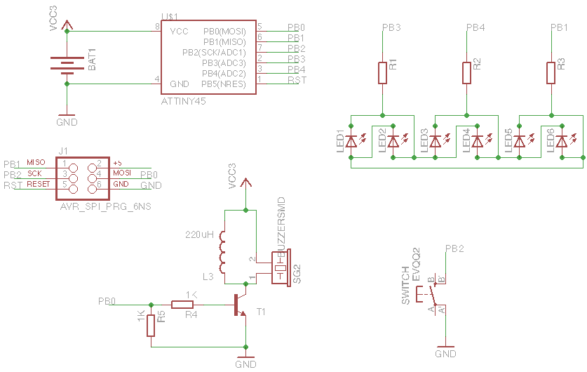
The resulting schematic follows.
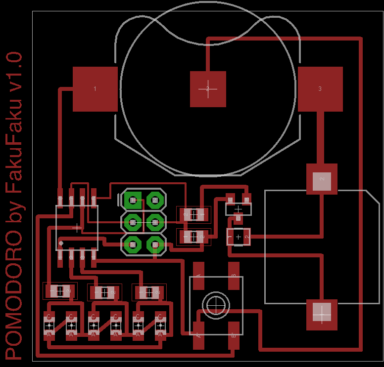
Board design
My goal was to print the circuit board a the ACI Atelier pour le routage et la fabrication de circuits imprimés at my university. There is there a fabulously equipped PCB fabrication laboratory for students. The machines are from the 70’s and can print professional quality (for that era) circuit boards. I have been using it several time already and wanted this time to try some very fine details.
Also, I don’t like having to drill many holes in the PCB, so I went for an all SMD single-sided design. I picked the SOIC-8 version of the ATtiny85, generic 0805 resistors and LEDs. Maybe the notable element is this very neat SMD buzzer. However, this buzzer has no driving circuit integrated so I need to add this to the design (transistor and inductor). For programming, I added the footprint for a six-pin ISP header. The programming can then be done by pressing some pogo pins to the header footprint.
Here is the PCB that came out of fab. We can recognize on top the footprint for the coin cell holder. The board is about 4x4 cm.
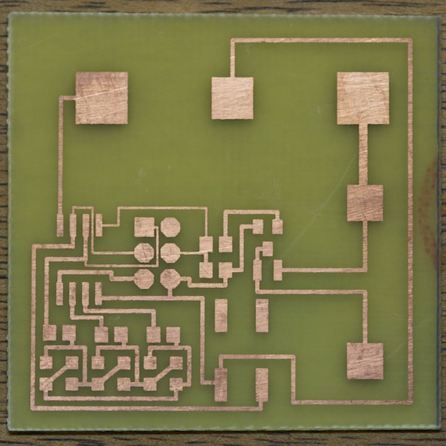
The finest tracks here are only 0.2 mm wide. For such precision, the bottleneck is the mask. I use transparency sheets with the mask printed on a generic laser printer. To obtain very opaque mask, it is important to select transparency paper and overlap two prints.
I was also very happy with the very regular Charlieplexing design I obtained, and visible in the lower left.
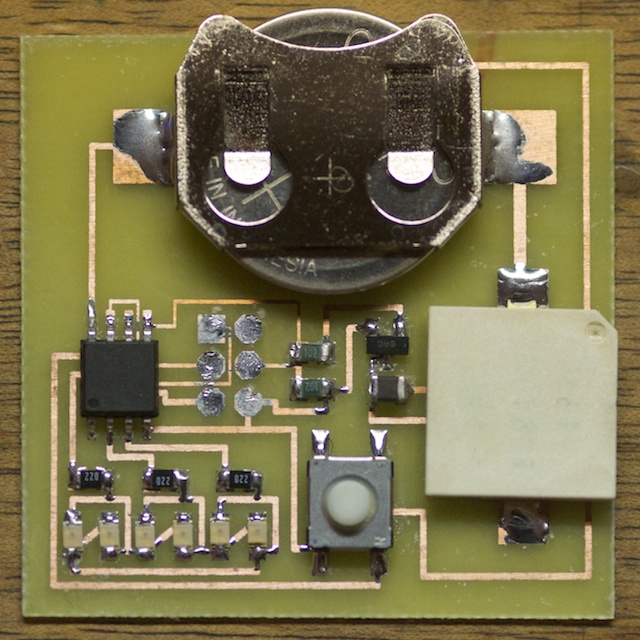
Here is the final product with all components soldered.

Code design
Here is how we would like our gadget to behave.
- One click starts a 25 minutes work counter. Five yellow LED indicates how many slices of five minutes are left. There is a discrete beep when the timer expires. The LED then flashes to remind you to go into rest mode. It is also possible to skip to rest before the end of the counter by pressing the button.
- A second click starts a 5 minutes rest counter. A red LED is turned on. There is a discrete beep when it expires. Then the timer turns off.
- If you wish the turn the timer off during rest mode, click a third time the button.
The code is completely interrupt driven. TIMER1 and its overflow interrupt are used to keep track of time during each state. The tactile switch triggers an interrupt to wake up the AVR, or switch between states. The finite state machine looks like this. Blue arrows are state switching triggered by a push on the button. Red arrows are switching caused by the timer expiration.
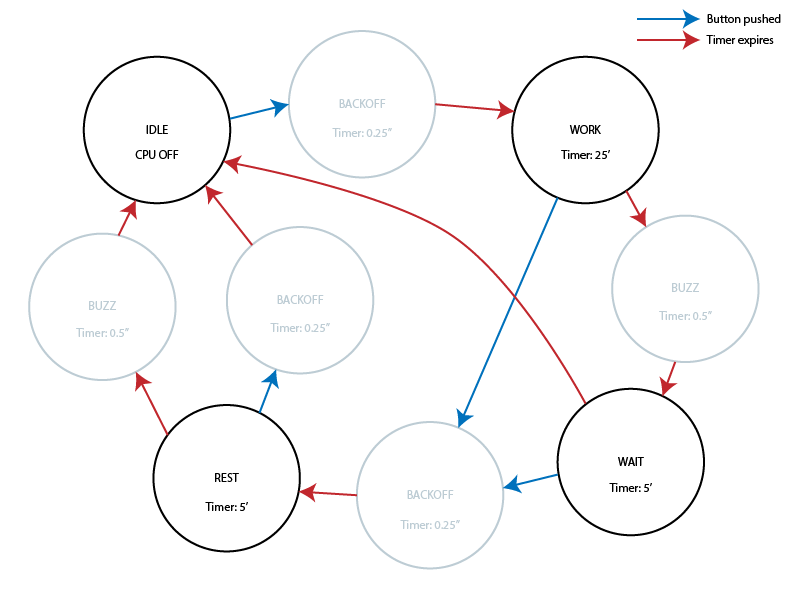
The main states are black circles. The grey circles are the transition states.
It was important to add the BACKOFF state to debounce the tactile button because it triggered multiple interrupts.